

Today I begin my week #7 of Fablab Academy and in comparison to last week, this one is totalle different. This week is about Computer-Controlled Machining. So this means I have to design and make something big. In this week I will be learning how to use a new machine, the Shop bot and the semi automatic router. I think of all the machines i've been waiting for the shop bot and getting to know it, i'm a little curious too about the semi automatic router. So let´s start with this week assignments and hope for the best.
This week assignmets are:
Group assignments:
Individual assignments:
What will I need for this week assignments:

ShopBot CNC
A CNC (computer numeric control) tool is used in prototyping and full production for cutting, carving, machining and milling in a variety of materials including wood, mdf, plastics, foams and aluminum. ShopBot Tools, like all CNC tools, move a cutter around a big table (X and Y axes) and move it up and down as well (Z axis) allowing it to make 3D movements and cut all sorts of shapes. The cutter looks like a drill bit and is spun by a motor called a router or spindle.
It can create virtually any pattern or shape and will do it in materials such as wood, plastic, foam, aluminum and many composites. You use the included software to design your parts on your personal computer, then, like a robot, the computer controls the cutter to precisely cut your parts. Now, all the types of computer-driven tools that create things by cutting material away (such as CNCs or laser cutters) or building up material in layers to create an object (3D printing) are called digital fabrication tools.
Unlike a drill bit, a router bit is designed to cut from the sides as well as the tip. By precisely moving the cutter through material, it can create virtually any pattern or shape and will do it in materials such as wood, plastic, foam, aluminum and many composites.
Data from: ShopBot CNC

ShopBot CNC
Autodesk Fusion combines CAD, CAM, CAE, and PCB into a single, integrated cloud software platform. It includes all the tools that you need to go from design to manufacturing, seamlessly.
With Autodesk Fusion, you'll be able to:
Data from: Fusion 360
This safety summary contains general safety warnings that should be understood during operation of this machine. Failure to observe these precautions could result in injury.

Learn and understand safe use of the machine. Do not allow untrained individuals to operate the machine without supervision. Be aware of the location of the Emergency Stop switches at all times.

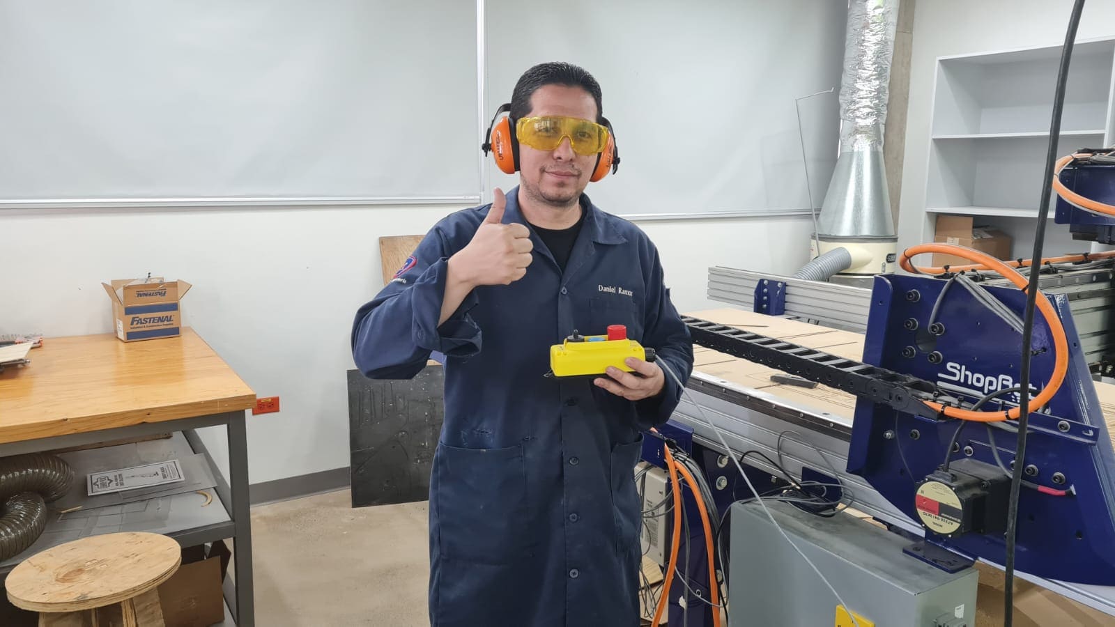
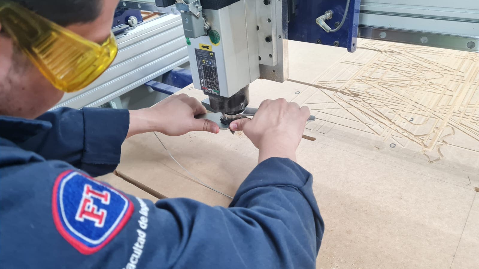
Eye and ear protection MUST be worn by the machine operator as well as any bystanders or observers. Flying sawdust, material chips, and other debris can cause serious eye injury.
Wear closed-toe shoes at all times.

Make sure that material is properly secured before cutting and be aware of any small parts that may come loose after being cut. If a small part catches the edge of a spinning bit, it can be thrown forcefully in any direction, causing injury or damage.
Never place your hands on the rails of the ShopBot. Be aware that the machine may move unexpectedly in any direction, which can cause serious injury if your hands are in the path of movement.

Never wear gloves while operating the machine. As with any power tool, a glove can get caught in moving or spinning parts and pull your hand into the machinery.

Never leave a machine running and unattended. Understand that a spinning tool generates friction and heat, creating a risk of fire. This risk is minimized by using correct chip load, using sharp bits, and by always double-checking your files before cutting. Be prepared to pause or stop the cut if something seems incorrect or unsafe.
Keep a working fire extinguisher within reach of the machine, for the reasons listed above.

Do not use cel phone while operating the ShopBot.
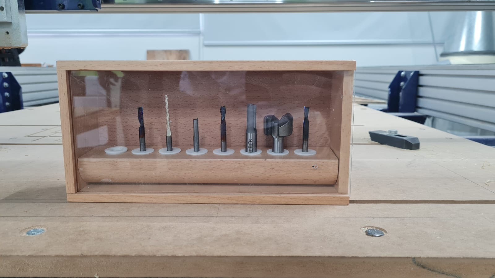
In this section, I'll show the measures, equipment I will use and how to change the milling bits. So let's begin:
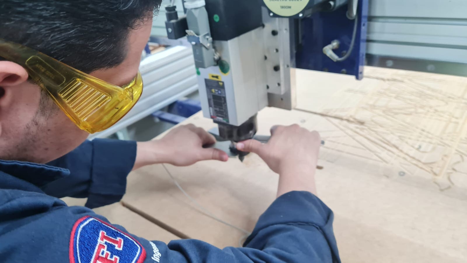
So I dress up before I start my cutting assignments in the ShopBot. As you see I have the necessary security equipment as recommended in section A1:
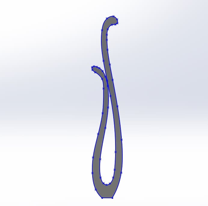
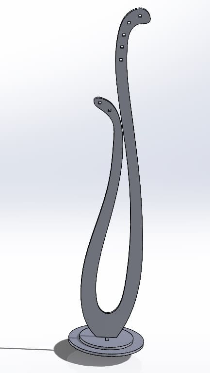
For this weekly assignments I have to design something big and then cut it in the ShopBot. I decided to make a coat rack. So lets begin with the design.
Some characteristics about the design:
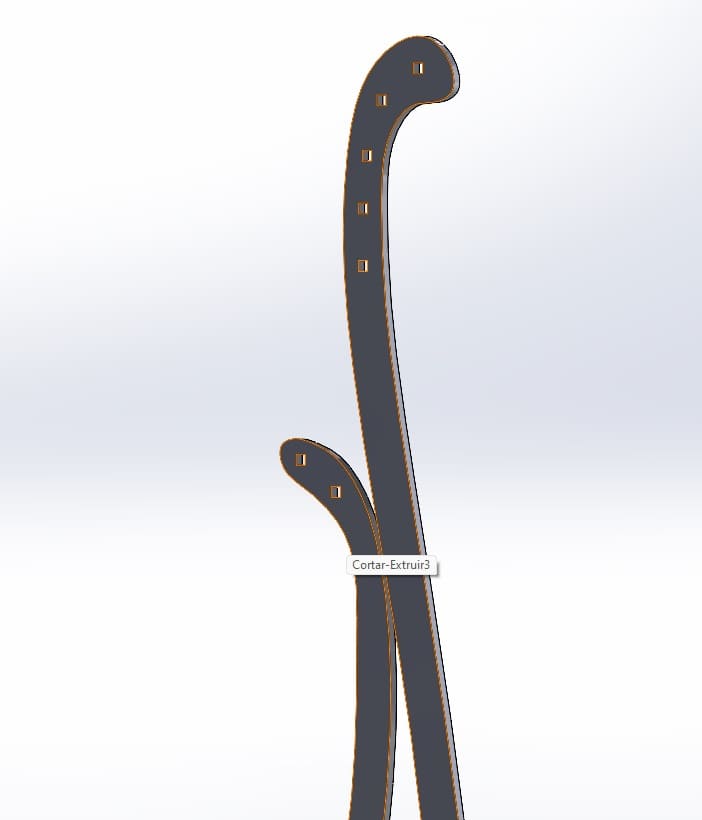
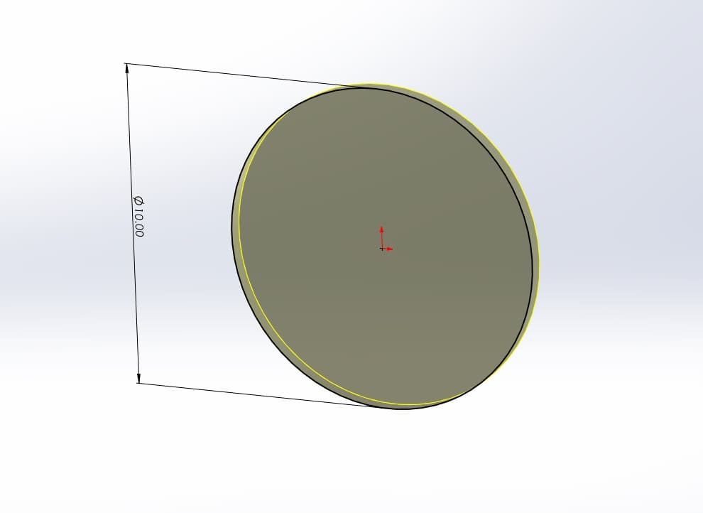
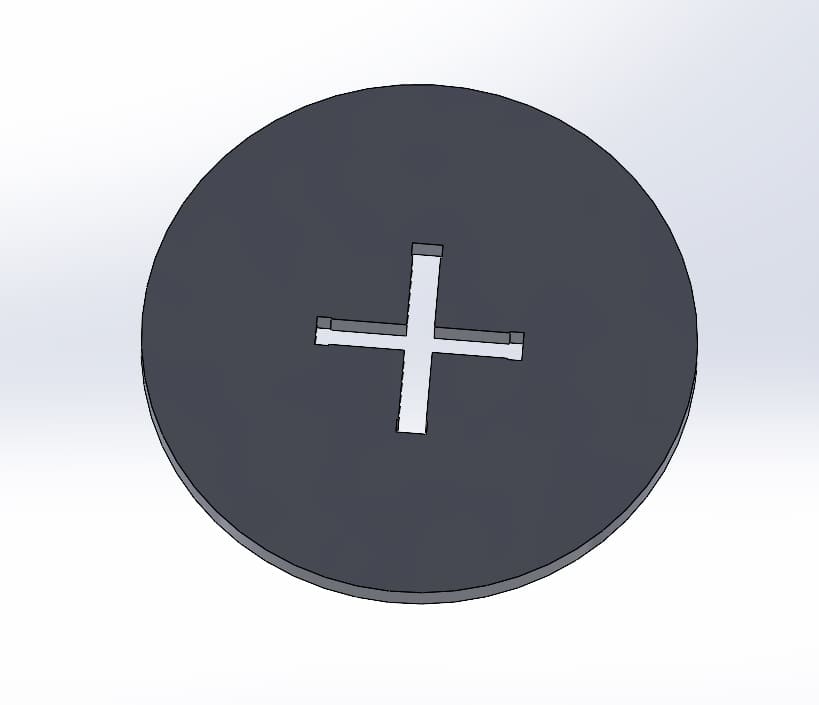
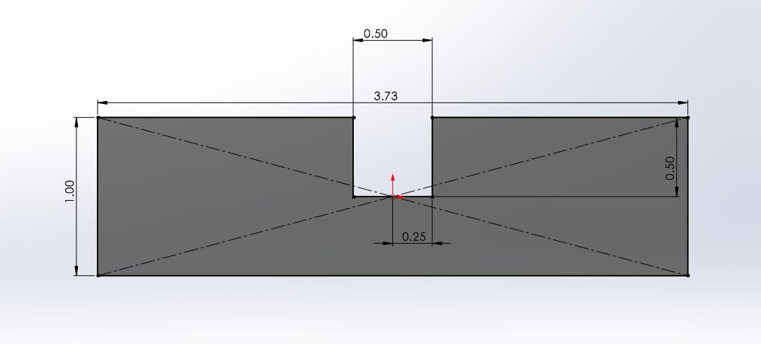
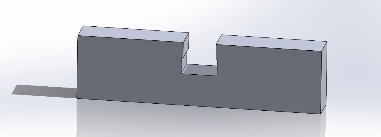

In this part I'll show the previous configurations of the ShopBot using Fusion 360. First of all, you need to install Desktop Fusion 360.
Now lets start with the configuration:
Were done eith the first part, now it's necessary to add libraries and mills that I'll be using with the ShopBot.
Lets begin with this second part of the settings:
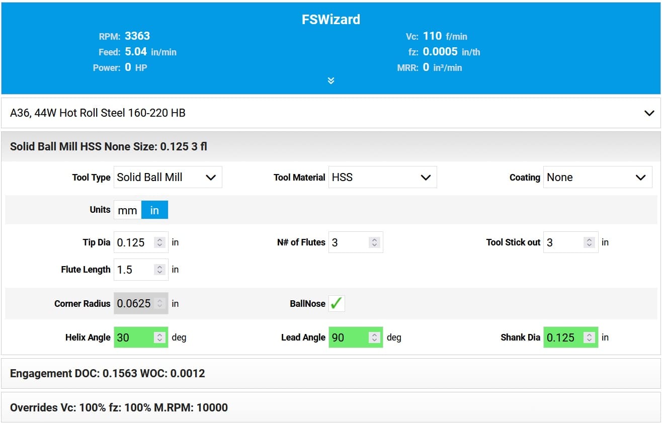
In this third part I'll show the results of the calculations for the speed and feed values for the machining process. For these calculations, I'm using this web page: HSM advisor, which helps calcualte a free CNC parameter calculator. For the end mill, I got the following parameters:

In this section I'll explain what I did before I start cutting my design. As I told you before it's very important to getting to know the machine, how it works, what can we do with it and of course the safety measures/protocols in case of any emergency. In the video you can see the previous configurations of the ShoBot, lets begin:
Here's a video of the ShoBot configuration
This is the moment of truth.... lets start cutting the coat rack. But before, just one more test before I start cutting. So I simulate the cutting process in the air and verify everything was ok, I share the video. As you can see in the video there were no problems.
Now, the moment of truth.... my final cutting in the ShopBot.. Here's a video that shows different moments during the cutting.
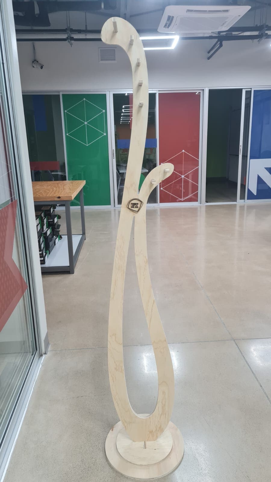
I decided to put a logo from the Faculty of Engineering, the final result has no fasteners and no glue, here´s the final result:

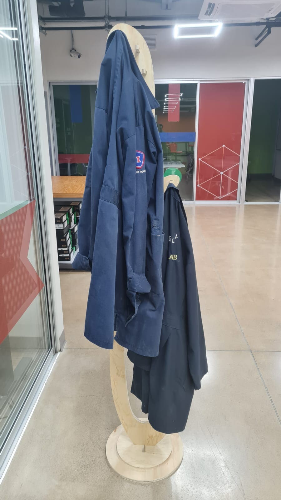
This was a very interesting week. But it's important to understand that "things happen" and its a way to learn about materials, machines, procedures and configurations.
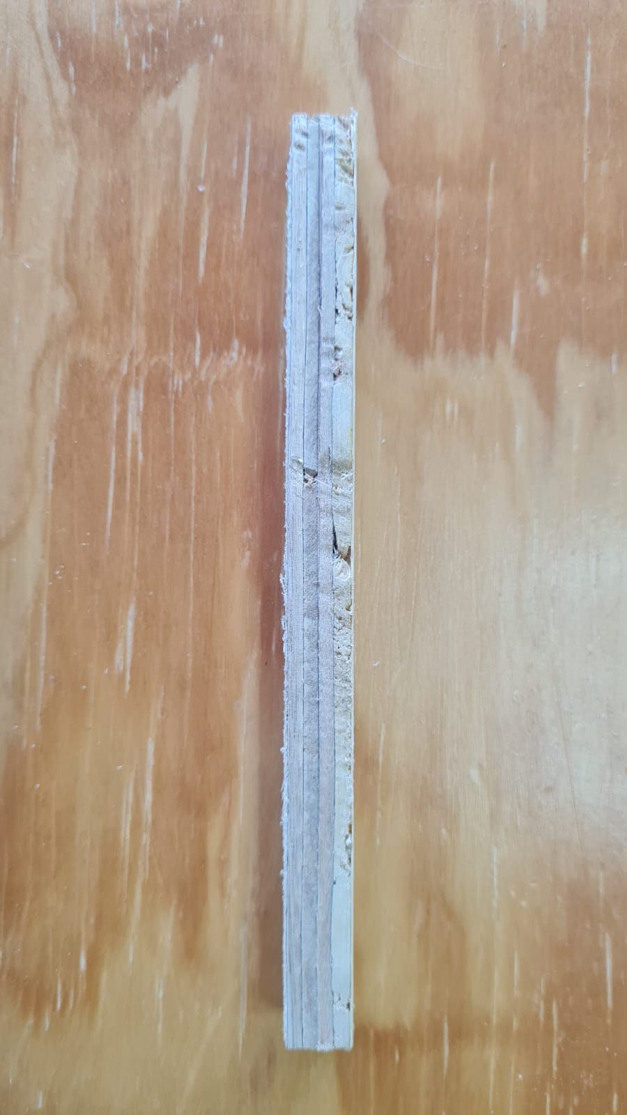
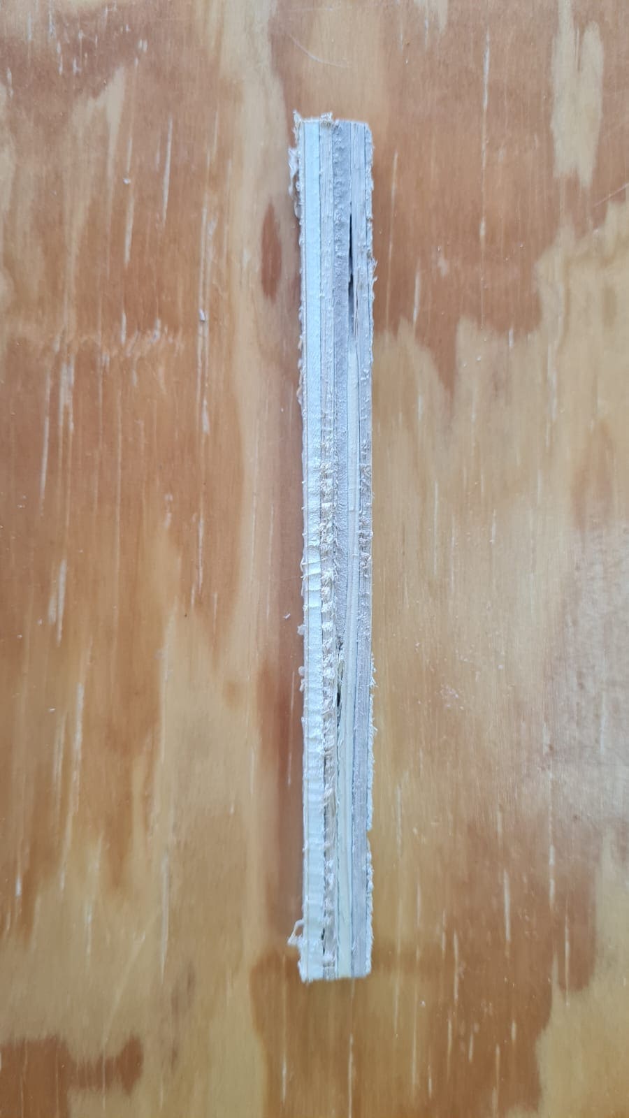
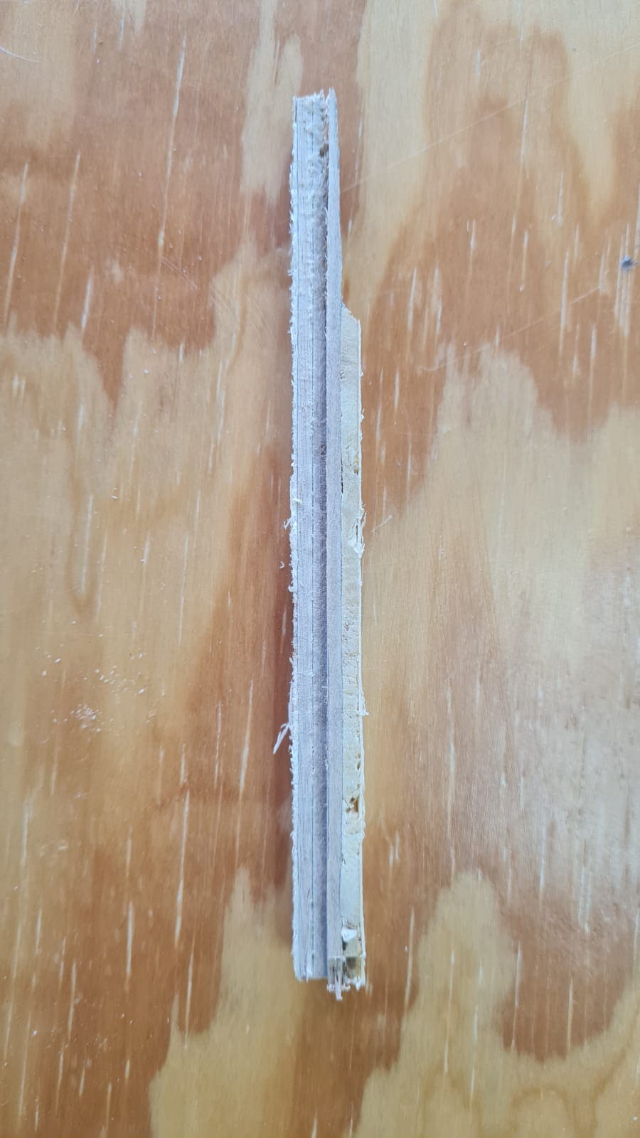
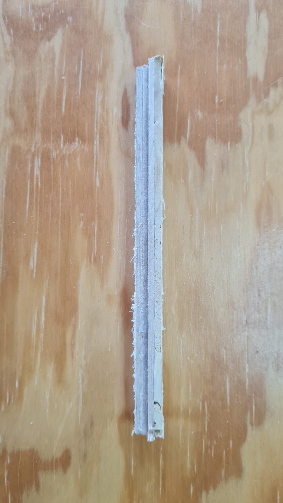
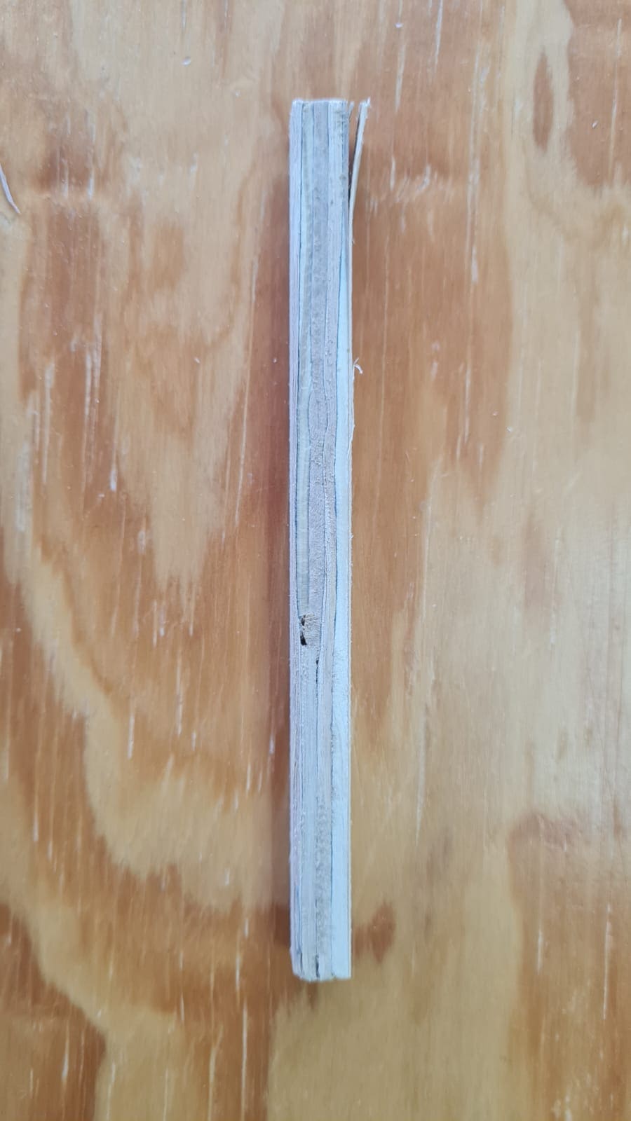
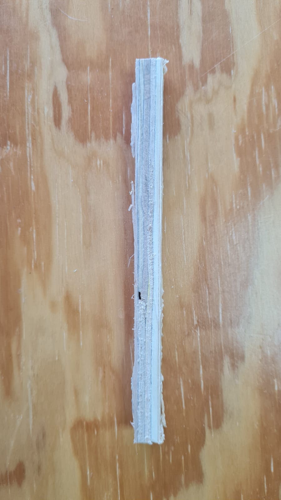
During this week assignments, some problems came along. So let me tell you about them and what I did to solve them.
In this part you can download the files that I use for this 7th week assignments.
What did I learn in this week?